717 Multiplexed clock
717 : Multiplexed clock
- Author: Gustavo Gomez
- Description: Multiplexed clock with buttons
- GitHub repository
- Clock: 32728 Hz
How it works
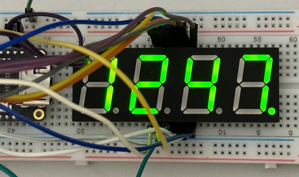
Basically this is a clock that counts minutes shows the hours in the 24-hour format, it uses the dot in the 7 segments to indicate 15s 30s 45s and 60s respectibly.
     -- 0 --         -- 0 --         -- 0 --         -- 0 --
    |       |       |       |       |       |       |       |
    5       1       5       1       5       1       5       1
    |       |       |       |       |       |       |       |
     -- 6 --         -- 6 --         -- 6 --         -- 6 --
    |       |       |       |       |       |       |       |
    4       2       4       2       4       2       4       2
    |       |       |       |       |       |       |       |
     -- 3 --  :60s   -- 3 --  :45s   -- 3 --  :30s   -- 3 --  :15s
        ↑               ↑               ↑               ↑
      Hours H         Hours L         Minutes H       Minutes L
    uio_out[3]      uio_out[2]       uio_out[1]      uio_out[0]
[6:0] of the seven segments are connected to the uo_out output and the 7 bit is for the dot of the seven sevements. The digist are multiplexed, each digit is shown 1ms, those pins are uio_out[3:0] and uio_out[5:4] are used for debuging showing the clock of the seconds and minutes.
For the test i have used this 7 segment with common Cathode. But you can use which ever 7 segmnet display of 4 digits common or anode thats to the pins ui_in[3:2] with are use to negate the 7 segmetents or the multixplexing. Finally, ui_in[1:0] are used with a button to increase the hours or minutes.
How to test
I have selected a clock 32,768khz because i thought it will be easy to buy a ready commponent that generates a squera wave with that frecuency, we will see about that :stuck_out_tongue_closed_eyes:. Just connect the 7 segments to the uo_out pins and select your configuration anode or catothe with the ui_in[3] pin. For the multiplexing connected uio_out[3:0] to the digits as show in how to use drawing.
And finally if you want to increase the numbers connect a button pull up to the pins ui_in[1:0] to increase hours or minutes.
Generate a reset to start to init all the registers.
External hardware
7 segment 4 digits multiplexed
IO
| # | Input | Output | Bidirectional |
|---|---|---|---|
| 0 | pull up button that increases minutes | segment a | output multiplex first digit |
| 1 | pull up button that increases hours | segment b | output multiplex second digit |
| 2 | pin used to negate 7 segment ouputs if necesary / for catode or anode configurations | segment c | output multiplex third digit |
| 3 | pin used to negate 4 pins to multiplex if necesary / for catode or anode configurations | segment d | output multiplex forth digit |
| 4 | segment e | output clock of seconds / testing purposes | |
| 5 | segment f | output clock of minutes / testing purposes | |
| 6 | segment g | output not used | |
| 7 | dot | output not used |